Masters Degree in Guidance and Navigational Contro...More
Sections

Figure1: Power Triangle
The value of power factor may vary from zero to one and the ideal value is unity. Any value of power factor below than unity means additional power is needed to do a particular task. Current flow causes loss in the supply as well as distribution system. The loading of supply is done more efficiently when the power factor is unity. As the power factor reduces the losses increase. For instance, if the power factor is 0.8 the losses in the system will increase as more current is drawn to do a task which can be done with much lesser current at unity power factor. A slight increase in power factor from 0.8 will considerably reduce the losses as the losses are proportional to the square of the current.
When the power factor is less than unity, the missing power is known as the reactive power which is needed for providing a magnetising field for inductive loads to perform a particular function. The reactive power is also known as wattless power or wasted or magnetising power and it causes an extra burden on electricity supply system and consumer’s bill.
A poor power factor is as a result of considerable difference in phase between voltage and current at load end. It may also result from high harmonics or distorted current waveform. Inductive loads such as induction motor, power transformer, ballast in luminaries, a winding set etc. are the causes for poor power factor. Distortion in current waveform may be due to rectifier, inverter, variable speed drives, switch mode power supplies etc. Poor power factor due to inductive loads can be improved by the addition of power factor correction equipment, but a poor power factor due to a distorted current waveform requires a change in equipment design or the addition of harmonic filters. Some inverters are quoted as having a power factor of better than 0.95 when, in reality, the true power factor is between 0.5 and 0.75. The figure of 0.95 is based on the cosine of the angle between the voltage and current but does not take into account that the current waveform is discontinuous and therefore contributes to increased losses.
An inductive load requires a magnetic field to operate and in creating such a magnetic field causes the current to be out of phase with the voltage (the current lags the voltage). Power factor correction is the process of compensating for the lagging current by creating a leading current by connecting capacitors to the supply. A sufficient capacitance is connected so that the power factor is adjusted to be as close to unity as possible thus reducing the losses.
To reduce the losses in the distribution system and to reduce the electricity bill, power factor correction, usually in the form of capacitor, is added to neutralise the magnetising current as much as possible. Capacitors contained in most power factor improvement devices draw current that leads the voltage thus resulting in a leading power factor. Extend of lag of a circuit that operates in lagging power factor is considerably reduced by connecting capacitors in parallel to that circuit. Typically the corrected power factor will be in the range of 0.92 to 0.95. Some power distributors offer incentives to the consumers who maintain a power factor above 0.9 where as some distributors penalize the consumers with poor power factor. There are many ways to measure the power factor to reduce the energy wastage in distribution system. Power distribution companies encourage the consumers to use power factor correction equipment.
The benefits that can be achieved by applying the correct power factor correction are:
Static Capacitors
Most of the industrial and power system loads are inductive that take lagging current which decreases the system power factor thus decreasing the efficiency. To improve the power factor static capacitors are connected in parallel with those devices which work on low power factor. Static capacitors provide leading current that neutralizes the lagging inductive component of load current. Static capacitors are installed in vicinity of large inductive loads like induction motor transformer etc. Capacitor current is 1800 out of phase from the load’s inductive contribution to current draw. The capacitor’s reactive power will directly subtract from the loads reactive power.
Total KVAR = Inductive KVAR - Capacitive KVAR
This correction will not change the amount of true power consumed by the load, but will result in a substantial reduction of apparent power and of the total current drawn from the 230V source.
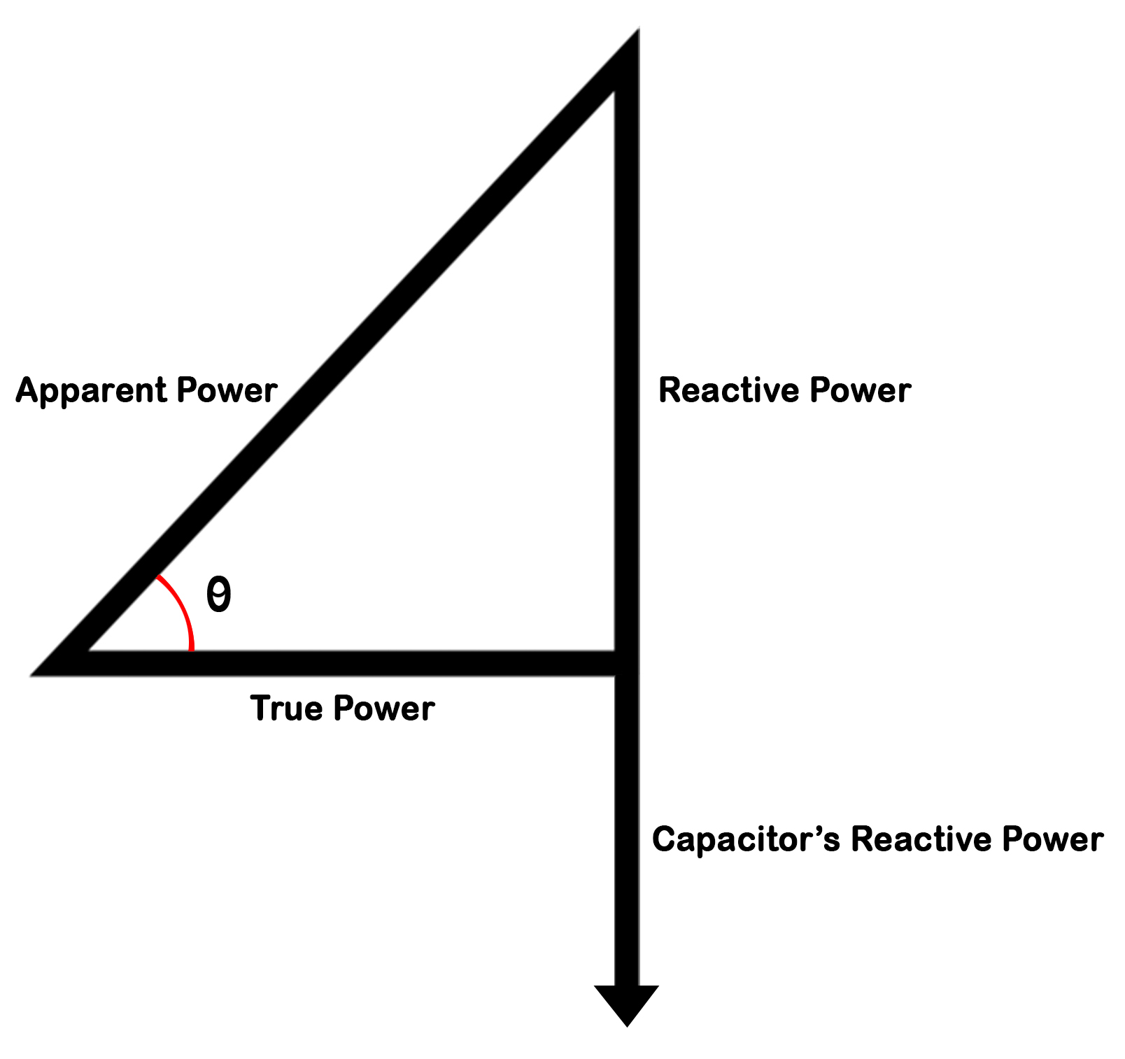
Figure2: Power Triangle with Static Capacitor
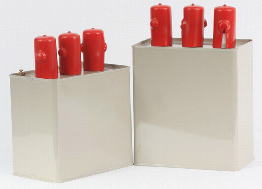
Figure 3: Static Capacitors
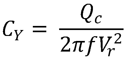
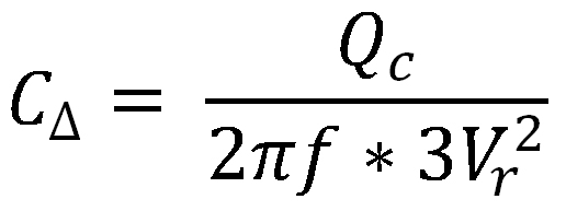
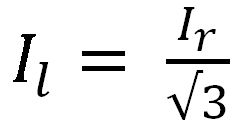
The two configurations for connecting capacitor banks are Star connection and Delta connection. Delta connected capacitor banks are usually used for voltages of 2400V or less. In 3phase system in order to supply the same reactive power, the star connected capacitor bank requires capacitor with a capacitance three time that of a delta connected capacitor bank. The capacitor in star connected capacitor bank will be subjected to a voltage √3 times lower and a current √3 times higher than the capacitor in the delta connected capacitor bank.
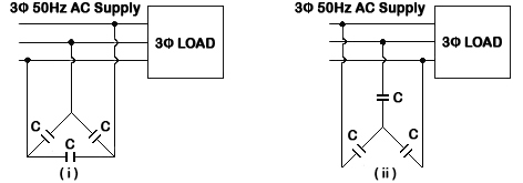
Figure 4: Configuration of Capacitor Bank. (i) Delta Connection (ii) Star Connection
When a synchronous motor operates at no-load and over excited then it is called a synchronous condenser. When synchronous motor is over excited it provides leading current and works like a capacitor. Synchronous Condensers are used for power factor improvement in large industries.
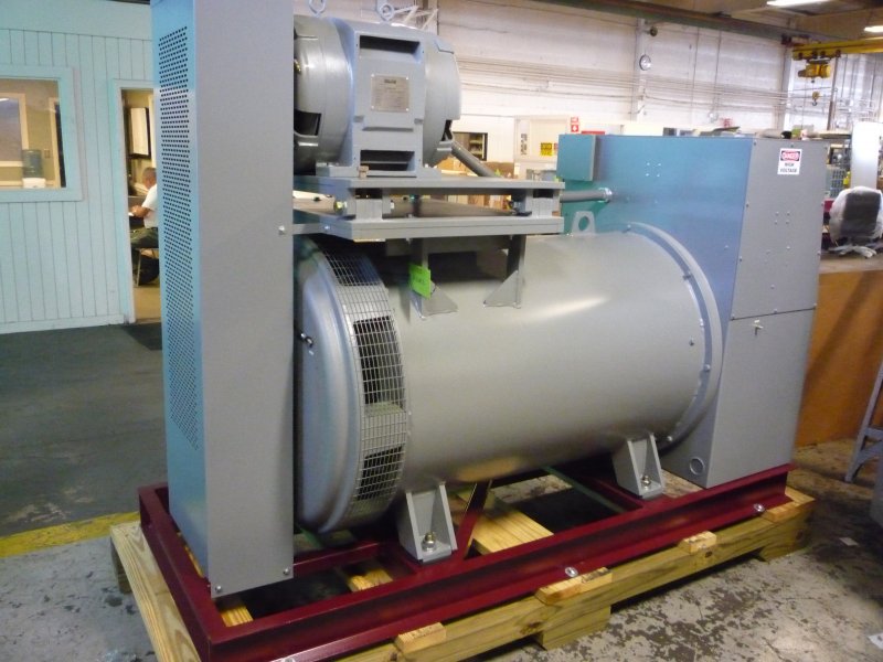
Figure 5: Synchronous Condenser
Phase advancer is a simple AC exciter connected to the motor shaft and operates with the motor’s rotor circuit for power factor improvement. Phase advancers are used in industries for the power factor correction of induction motors.
Figure 6: Phase Advancer

Figure 7: Electric Circuit whose power factor is to be measured
In the above circuit, wattmeter gives true power in KW
Apparent power can be found by multiplying load voltage and load current obtained from the ammeter.
Selection of Capacitor Bank for Power Factor Improvement
CosØ1: Actual Power Factor
CosØ2: Required Power Factor
P: Input Power
V: Load Voltage
QC: Capacitor Reactive Power
F: Frequency
C: Equivalent capacitance of Capacitor Bank
XC = Capacitive Reactance
Required Capacitor KVAR to improve power factor from CosØ1 to CosØ2 is given by
QC = P (TanØ1 – TanØ2)


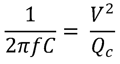
Therefore Capacitance required for the capacitor is given by

Capacitor for star connected capacitor bank CΥ is given by
Rated current of the component
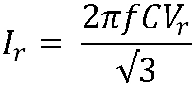
Line Current

Capacitor for delta connected capacitor bank CΔ is given by
Rated current of the component

Line Current
Sections